Showing posts with label VHDL. Show all posts

Tuesday, October 14, 2014

VHDL Codes for Train Controller using State Machine

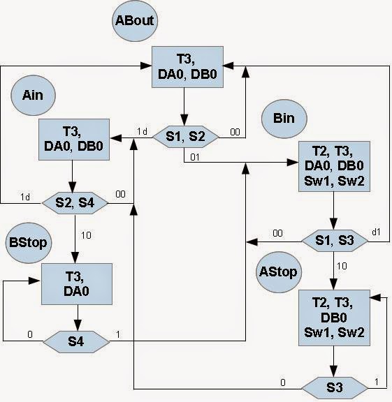
ASM Train Controller VHDL
Fig 1. ASM Diagram of Electric Train Controller
This posting will discuss a working example of a train controller using state machine. In this controller, two trains run counterclockwise at various speeds and avoid collisions. One train (A) runs on the outer track and the other (B) runs on the inner track. Only one train at a time is allowed to occupy the common track.

An ASM chart and State Machine diagram shown in figure 1 (above) and figure 2 contain the same information and describe algorithm of the train controller. In the ASM chart, state names, ABout, Ain, Bin, Bstop, Astop indicate the active and possible states. The rectangles contain the active (High) outputs for the given state. Outputs not listed are inactive (Low). The diamond shapes in the ASM chart indicate where the state machine tests the condition of the inputs (S1, S2, etc.). When two signals are shown in a diamond, they are both tested at the same time for the indicated values.

A state machine classic bubble diagram is shown in Figure 2 below. In the same names "in" and "out" refers to the state of track 2, the track that is common to both loops.


Description of The State Machine for Electric Train Controller
State machine Train Controller VHDL
Fig. 2  State Machine Diagram of Electric Train Controller

Saturday, July 12, 2014

Hierarchical Design in VHDL

[1] Functions 

Functions are a simple way of encapsulating behavior in a model that can be reused in multiple architectures. Functions can be defined locally to an architecture or more commonly in a package, but in this section the basic approach of defining functions will be described. The simple form of a function is to define a header with the input and output variables as shown below:

      function name (input declarations) return output_type is
           ... variable declarations
      begin
           ... function body
      end

For example, a simple function that takes two input numbers and multiplies them together could be defined as follows:
             
      function mult (a, b: integer) return integer is
      begin
           return a * b;
      end; 

[2] Packages 

Packages are a common single way of disseminating type and function information in the VHDL design community. The basic definition of a package is as follows:

      package name is
           ... package header contents
      end package;
      package body name is
      begin
           ... package body contents
      end package body;

As can be seen, the package consists of two parts, the header and the body. The header is the place where the types and functions are declared, and the package body is where the declarations themselves take place.

For example, a function could be described in the package body and the function is declared in the package header. Take a simple example of a function used to carry out a simple logic function:

      and10 = and(a, b, c, d, e, f, g, h, i, j)

The VHDL function would be something like the following:

      function and10 = and(a,b,c,d,e,f,g,h,i,j: bit) return bit is 
      begin
        return a and b and c and d and e and f and g and h and i and j;
      end;

The resulting package declaration would then use the function in the body and the function header in the package header thus:
   
      package new_functions is 
      function and10 = and(a,b,c,d,e,f,g,h,i,j: bit) return bit;
      end;
      package body new_functions is       
         function and10 = and(a,b,c,d,e,f,g,h,i,j: bit) return bit is;
           begin
              return a and b and c and d and e \ 
                  and f and g and h and i and j;
           end;
      end;


[3] Components

While procedures, functions and packages are useful in including behavioral constructs generally, with VHDL being used in hardware design context, often there is a need to encapsulate design blocks as a separate component that can be included in a design, usually higher in the system hierarchy.

To be continued


[4] Procedures

Procedures are similar to functions, except that they have more flexibility in the parameters, in that the direction can be in.

To be continued
Saturday, June 14, 2014

Decisions and Loops in VHDL

[1] If- Then - Else
The basic syntax for a simple if statement is as follows:

            signal (condition) then
           ...statements
      end if;

The condition is a Boolean expression, of the form a > b or a = b. Note that the comparison operator for equality is a single =, not to be confused with the double == used in some programming languages. For example, if two signals are equal, then set an output high would be written in VHDL as:

            if (a = b) then
            out1 <= `1';
      end if;
If the decision needs to have both the if and else options, then the statement is extended as follows:
      
      if (condition) then
           ...statements
      else
           ...statements     
      end if;
So in the previous example, we could add the else statements as follows: 

            if (a = b) then
           out1 <= `1';
      else
           out1 <= `0';     
      end if;

And finally, multiple if conditions can be implemented using the general form:
      
      if (condition1) then
           ...statements
      elseif (condition2)
           ...statements 
           ...more elsif conditions & statements     
      else
           ...statements
      end if;

With an example: 
      
      if (a > 10) then
           out1 <= `1';
      elseif (a > 5) then
           out1 <= `0';    
      else
           out1 <= `1';
      end if;


[2] Case
IF statement is relatively simple to define multiple conditions, but it becomes a little cumbersome, and so the case statement offers a simple approach to branching, without having to use Boolean conditions in every case. This is especially useful for defining state diagrams or for specific transitions between states using enumerated types. An example of a case statement is:

      case testvariable is
         when 1 =>
            out1 <= '1';
     
         when 2 =>
            out2 <= '1';

         when 3 =>
            out3 <= '1';
      end case;

Wednesday, June 11, 2014

Basic Variable Types and Operators in VHDL

This section will discuss on Constants, Signals, Variables, Boolean Operators, Arithmetic Operators, Comparison Operators, Shifting Functions and Concatenation in VHDL.

[1]. Constants
Element type of constants will be used when a value needs to be static throughout a simulation. Constants often used to initialize parameters or to set fixed register values for comparison. A constant can be declared for any defined type in VHDL with examples as follows;

     constant a : integer := 1;
     constant b : real := 0.123;
     constant c : std_logic := `0';    


[2]. Signals
Signals are the link between processes and sequential elements within the processes. Signals are effectively "wires" in the design and connect all the design elements together.
Signals can be assigned immediately or with a time delay, so that an event is scheduled for sometime in the future (after the specified delay). It is also important to recognize that signals are not the same as a set of sequential program code, but are effectively concurrent signals that will not be able to be considered stable until the next time the process is activated.
Examples of signal declaration and assignment are shown below:
     
     signal sig1 : integer := 0;
     signal sig2 : integer := 1;
     sig1 <= 14; 
     sig1 <= sig2; 
     sig1 <= sig2 after 10 ns;  

Monday, March 3, 2014

Process: Basic Functional Unit in VHDL

basic-functional-unit-VHDL
The process in VHDL is the mechanism by which sequential statements can be executed in the correct sequence, and with more than one process, concurrently. Each process consists of a sensitivity list, declarations and statements. The basic process syntax is given below:

     process sensitivity_list is
          ... declaration part
        
     begin
          ... statement part
         
     end process;


The sensitivity list allows a process to be activated when a specific signal changes value, for example a typical usage would be to have a global clock (clk) and reset (rst) signal to control the activity of the process, for example:

     process (clk, rst) is
        
     begin
          ...process statements
         
     end process;


In this example, the process would only be activated when either clk or rst changed value. Another way of encapsulating the same behavior is to use a wait statement in the process so that the process is automatically activated once, and then waits for activity on either signal before running the process again. The same process could then be written as follows:

Wednesday, February 26, 2014

Architecture: Behavioral Modelling in VHDL

behavioral-modelling-VHDL

1. Basic Definition of an Architecture

While the entity describes the interface and parameter aspects of the model, the architecture defines the behavior. There are several types of VHDL architecture and VHDL allows different architectures to be defined for the same entity. This is ideal for developing behavioral, Register Transfer Level RTL and gate Level architectures that can be incorporated into designs and tested using the same test benches.

The basic approach for declaring an architecture could be as follows:
 
     architecture behaviour of test is
         ..architecture declarations
         
      begin
          ..architecture contents

     end architecture behaviour;

Or
          
     architecture behaviour of test is
          ..architecture declarations
      
      begin
          ..architecture contents
        
     end behaviour;

Monday, February 24, 2014

Entity: Interface Model in VHDL

vhdl-structure-interface-model

1. Entity Definition

The entity defines how a design element described in VHDL connects to other VHDL models and also defines the name of the model. The entity also allows the definition of any parameters that are to be passed into the model using hierarchy. Figure beside is overall structure of a VHDL module. 

The basic template for an entity is as follows:

     entity <name> is 

          ...

     entity <name>;
  
If the entity has the name "test", then the entity template could be either: 
     entity test is
     end entity test

or:
      entity test is
     end test;


2. Ports

The method of connecting entities together is using PORTS. These are defined in the entity using the following method:
      port(
      ... list of port declarations...
      );

The port declaration defines the type of connection and direction where appropriate. For example, the port declaration for an input bit called in1 would be as follows:
      in1 : in bit;

Tuesday, December 3, 2013

Dynamic Shift Registers

// Verilog Coding
// 16-bit dynamic shift register.
// -------------------------------------------------------------

module v_dynamic_shift_registers_1 (Q,CE,CLK,D,A);
    input CLK, D, CE;
    input [3:0] A;
    output Q;
    reg [15:0] data;

    assign Q = data[A];

    always @(posedge CLK)
    begin
        if (CE == 1'b1)
            data <= {data[14:0], D};
    end

endmodule