Showing posts with label HDL Coding. Show all posts

Tuesday, October 14, 2014

VHDL Codes for Train Controller using State Machine

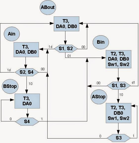
ASM Train Controller VHDL
Fig 1. ASM Diagram of Electric Train Controller
This posting will discuss a working example of a train controller using state machine. In this controller, two trains run counterclockwise at various speeds and avoid collisions. One train (A) runs on the outer track and the other (B) runs on the inner track. Only one train at a time is allowed to occupy the common track.

An ASM chart and State Machine diagram shown in figure 1 (above) and figure 2 contain the same information and describe algorithm of the train controller. In the ASM chart, state names, ABout, Ain, Bin, Bstop, Astop indicate the active and possible states. The rectangles contain the active (High) outputs for the given state. Outputs not listed are inactive (Low). The diamond shapes in the ASM chart indicate where the state machine tests the condition of the inputs (S1, S2, etc.). When two signals are shown in a diamond, they are both tested at the same time for the indicated values.

A state machine classic bubble diagram is shown in Figure 2 below. In the same names "in" and "out" refers to the state of track 2, the track that is common to both loops.


Description of The State Machine for Electric Train Controller
State machine Train Controller VHDL
Fig. 2  State Machine Diagram of Electric Train Controller

Wednesday, December 4, 2013

Shift Registers - VHDL

-- [1] 8-bit Shift-Left Register with Positive-Edge Clock, Serial In, and Serial Out
--------------------------------------------------------------------------------------------

library ieee;
use ieee.std_logic_1164.all;

entity shift_registers_1 is
    port(C, SI : in std_logic;
         SO : out std_logic);
    end shift_registers_1;

architecture archi of shift_registers_1 is
    signal tmp: std_logic_vector(7 downto 0);
begin

    process (C)
    begin
        if (C'event and C='1') then
            for i in 0 to 6 loop
                tmp(i+1) <= tmp(i);
            end loop;
            tmp(0) <= SI;
        end if;
    end process;

    SO <= tmp(7);

end archi;

Tuesday, December 3, 2013

Shift Registers - Verilog

// [1] 8-bit Shift-Left Register with Positive-Edge Clock,
// Serial In, and Serial Out
// ---------------------------------------------------------------

module v_shift_registers_1 (C, SI, SO);
    input C,SI;
    output SO;
    reg [7:0] tmp;

    always @(posedge C)
    begin
        tmp <= tmp << 1;
        tmp[0] <= SI;
    end

    assign SO = tmp[7];

endmodule

Dynamic Shift Registers

// Verilog Coding
// 16-bit dynamic shift register.
// -------------------------------------------------------------

module v_dynamic_shift_registers_1 (Q,CE,CLK,D,A);
    input CLK, D, CE;
    input [3:0] A;
    output Q;
    reg [15:0] data;

    assign Q = data[A];

    always @(posedge CLK)
    begin
        if (CE == 1'b1)
            data <= {data[14:0], D};
    end

endmodule

Dividers

// Verilog Coding
// Division By Constant 2
// -------------------------------

module v_divider_1 (DI, DO);
    input  [7:0] DI;
    output [7:0] DO;

    assign DO = DI / 2;

endmodule

Adders - VHDL


-- [1] Unsigned 8-bit Adder
----------------------------------

library ieee;
use ieee.std_logic_1164.all;
use ieee.std_logic_unsigned.all;

entity adders_1 is
    port(A,B : in std_logic_vector(7 downto 0);
         SUM : out std_logic_vector(7 downto 0));
end adders_1;

architecture archi of adders_1 is
begin

    SUM <= A + B;

end archi;

Adders - Verilog

// [1] Unsigned 8-bit Adder
// -----------------------------------

module v_adders_1(A, B, SUM);
    input [7:0] A;
    input [7:0] B;
    output [7:0] SUM;

    assign SUM = A + B;

endmodule

Accumulators


// Verilog Coding
// 4-bit Unsigned Up Accumulator with Asynchronous Clear
// -----------------------------------------------------------------

module v_accumulators_1 (C, CLR, D, Q);

    input C, CLR;
    input [3:0] D;
    output [3:0] Q;
    reg [3:0] tmp;
   
    always @(posedge C or posedge CLR)
    begin
        if (CLR)
            tmp = 4'b0000;
        else
            tmp = tmp + D;
        end
    assign Q = tmp;
endmodule


-- VHDL Coding
-- 4-bit Unsigned Up Accumulator with Asynchronous Clear
-- -----------------------------------------------------------------

library ieee;
use ieee.std_logic_1164.all;
use ieee.std_logic_unsigned.all;

entity accumulators_1 is
    port(C, CLR : in std_logic;
         D : in std_logic_vector(3 downto 0);
         Q : out std_logic_vector(3 downto 0));
end accumulators_1;

architecture archi of accumulators_1 is
    signal tmp: std_logic_vector(3 downto 0);
begin

    process (C, CLR)
    begin
        if (CLR='1') then
            tmp <= "0000";
        elsif (C'event and C='1') then
            tmp <= tmp + D;
        end if;
    end process;
   
    Q <= tmp;
   
end archi;