 |
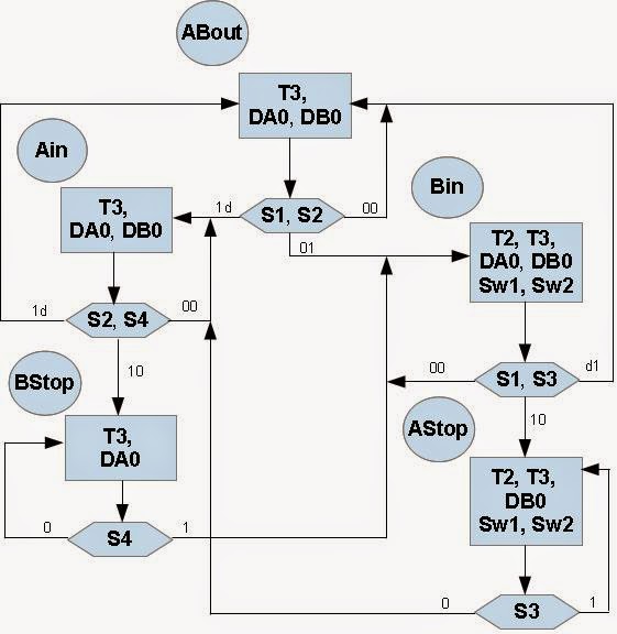
| Fig 1. ASM Diagram of Electric Train Controller |
An ASM chart and State Machine diagram shown in figure 1 (above) and figure 2 contain the same information and describe algorithm of the train controller. In the ASM chart, state names, ABout, Ain, Bin, Bstop, Astop indicate the active and possible states. The rectangles contain the active (High) outputs for the given state. Outputs not listed are inactive (Low). The diamond shapes in the ASM chart indicate where the state machine tests the condition of the inputs (S1, S2, etc.). When two signals are shown in a diamond, they are both tested at the same time for the indicated values.
A state machine classic bubble diagram is shown in Figure 2 below. In the same names "in" and "out" refers to the state of track 2, the track that is common to both loops.
Description of The State Machine for Electric Train Controller
All States
Description of The State Machine for Electric Train Controller
 |
| Fig. 2 State Machine Diagram of Electric Train Controller |
- T3 Asserted: The B power supply is assigned to track 3.
- All Signals that are not asserted are zero and imply a logic result as described.
- DA0 Asserted: Train A is on the outside track and moving counter-clockwise (forward).
- DB0 Asserted: Train B is on the inner track (not the common track) and also moving forward.
- Note that by NOT Assertig DA1, it is automatically zero--same for DB1. Hence, the outputs are DA = "01" and DB = "01".
Ain: "Train A moves to Common Track"
- Sensor 1 has fired either first or at the same time as Sensor 2.
- Either Train A is trying to move towards the common track, or
- Both trains are attempting to move towards the common track.
- Both trains are allowed to enter here, however, state Bstop will stop B if both have entered.
- DA0 Asserted: Train A is on the outside track and moving counter-clockwise (forward).
- DB0 Asserted: Train B is on the inner track (not the common track) and also moving forward.
Bstop: "Train B stopped at S2 waiting for Train A to clear common track"
- DA0 Asserted: Train A is moving from the outside track to the common track.
- Train B has arrived at Sensor 2 and is stopped and waits until Sensor 4 fires.
- SW1 and SW2 are NOT Asserted to allow the outside track to connect to common track.
- Note that T2 is not asserted making Track 2 tied to the A Power Supply.
Bin: "Train B has reached Sensor 2 before Train A reaches Sensor 1"
- Train B is allowed to enter the common track. Train A is approaching Sensor 1.
- DA0 Asserted: Train A is on the outside track and moving counterclockwise (forward).
- DB0 Asserted: Train is on the inner track moving towards the common track.
- SW1 Asserted: Switch 1 is set to let the inner track connect to the common track.
- SW2 Asserted: Switch 2 is set to let the inner track connect to the common track.
- T2 Asserted: The B Power Supply is also asserted to the common track.
Astop: "Train A stopped at S1 waiting for Train B to clear the common track"
- B0 Asserted: Train B is on the inner track moving towards the common track.
- SW1 and SW2 Asserted: Switches 1 and 2 are set to connect the inner track to the common track.
- T2 Asserted: The B Power Supply is also asserted to the common track.
| State | ABout | Ain | Astop | Bin | Astop |
|---|---|---|---|---|---|
| Sw1 | 0 | 0 | 1 | 1 | 0 |
| Sw2 | 0 | 0 | 1 | 1 | 0 |
| Sw3 | 0 | 0 | 0 | 0 | 0 |
| T1 | 0 | 0 | 0 | 0 | 0 |
| T2 | 0 | 0 | 1 | 1 | 0 |
| T3 | 1 | 1 | 1 | 1 | 1 |
| T4 | 0 | 0 | 0 | 0 | 0 |
| DA(1-0) | 01 | 01 | 00 | 01 | 01 |
| DB(1-0) | 01 | 01 | 01 | 01 | 00 |
VHDL Code for The State Machine of Electric Train Controller
The corresponding VHDL code for the state machine of train controller in Fig.2 is shown below. A CASE statement based on the current state examines the inputs to select the next state. At each clock edge the next state becomes the current state. WITH...SELECT statements at the end of the program specify the outputs for each state.
-- State Machine of Train Controller using VHDL
-- These libraries are required in all VHDL source files
----------------------------------------------------------------------------
LIBRARY IEEE;
USE IEEE.STD_LOGIC_1164.ALL;
USE IEEE.STD_LOGIC_ARITH.ALL;
USE IEEE.STD_LOGIC_UNSIGNED.ALL;
ENTITY Tcontrol IS
PORT (reset, clock, sensor1, sensor2, sensor3, sensor4, sensor5 :IN STD_LOGIC;
switch1, switch2, switch3 : OUT STD_LOGIC;
track1, track2, track3, track4 : OUT STD_LOGIC;
dirA, dirB : OUT STD_LOGIC_VECTOR(1 DOWNTO 0));
END Tcontrol;
ARCHITECTURE a OF Tcontrol IS
TYPE STATE_TYPE IS(ABout, Ain, Bin, Astop, Bstop);
SIGNAL state: STATE_TYPE;
SIGNAL sensor12, sensor13, sensor24: STD_LOGIC_VECTOR(1 DOWNTO 0);
BEGIN
PROCESS (reset, clock)
BEGIN
IF reset = '1' THEN
state <= ABout
ELSIF clock 'EVENT AND clock = '1' THEN
CASE state IS
WHEN ABout =>
CASE Sensor12 IS
WHEN "00" => state <= About;
WHEN "01" => state <= Bin;
WHEN "10" => state <= Ain;
WHEN "11" => state <= Ain;
WHEN OTHERS => state <= ABout;
END CASE;
WHEN Ain =>
CASE Sensor24 IS
WHEN "00" => state <= Ain;
WHEN "01" => state <= ABout;
WHEN "10" => state <= Bstop;
WHEN "11" => state <= ABout;
WHEN OTHERS => state <= ABout;
END CASE;
WHEN Bin =>
CASE Sensor13 IS
WHEN "00" => state <= Bin;
WHEN "01" => state <= ABout;
WHEN "10" => state <= Astop;
WHEN "11" => state <= ABout;
WHEN OTHERS => state <= ABout;
END CASE;
WHEN Astop =>
IF Sensor3 = '1' THEN
state <= Ain;
ELSE
state <= Astop;
END IF;
WHEN Bstop =>
IF Sensor4 = '1' THEN
state <= Bin;
ELSE
state <= Bstop;
END IF;
END CASE;
END IF;
END PROCESS;
-- Combine sensor bits for case statements above
-- "&" operator combines bits
sensor12 <= sensor1 & sensor2;
sensor13 <= sensor1 & sensor3;
sensor24 <= sensor2 & sensor4;
Track1 <= '0';
Track4 <= '0';USE IEEE.STD_LOGIC_1164.ALL;
USE IEEE.STD_LOGIC_ARITH.ALL;
USE IEEE.STD_LOGIC_UNSIGNED.ALL;
-- State Machine of Train Controller using VHDL
-- These libraries are required in all VHDL source filesENTITY Tcontrol IS
PORT (reset, clock, sensor1, sensor2, sensor3, sensor4, sensor5 :IN STD_LOGIC;
switch1, switch2, switch3 : OUT STD_LOGIC;
track1, track2, track3, track4 : OUT STD_LOGIC;
dirA, dirB : OUT STD_LOGIC_VECTOR(1 DOWNTO 0));
END Tcontrol;
ARCHITECTURE a OF Tcontrol IS
TYPE STATE_TYPE IS(ABout, Ain, Bin, Astop, Bstop);
SIGNAL state: STATE_TYPE;
SIGNAL sensor12, sensor13, sensor24: STD_LOGIC_VECTOR(1 DOWNTO 0);
BEGIN
PROCESS (reset, clock)
BEGIN
IF reset = '1' THEN
state <= ABout
ELSIF clock 'EVENT AND clock = '1' THEN
CASE state IS
WHEN ABout =>
CASE Sensor12 IS
WHEN "00" => state <= About;
WHEN "01" => state <= Bin;
WHEN "10" => state <= Ain;
WHEN "11" => state <= Ain;
WHEN OTHERS => state <= ABout;
END CASE;
WHEN Ain =>
CASE Sensor24 IS
WHEN "00" => state <= Ain;
WHEN "01" => state <= ABout;
WHEN "10" => state <= Bstop;
WHEN "11" => state <= ABout;
WHEN OTHERS => state <= ABout;
END CASE;
WHEN Bin =>
CASE Sensor13 IS
WHEN "00" => state <= Bin;
WHEN "01" => state <= ABout;
WHEN "10" => state <= Astop;
WHEN "11" => state <= ABout;
WHEN OTHERS => state <= ABout;
END CASE;
WHEN Astop =>
IF Sensor3 = '1' THEN
state <= Ain;
ELSE
state <= Astop;
END IF;
WHEN Bstop =>
IF Sensor4 = '1' THEN
state <= Bin;
ELSE
state <= Bstop;
END IF;
END CASE;
END IF;
END PROCESS;
-- Combine sensor bits for case statements above
-- "&" operator combines bits
sensor12 <= sensor1 & sensor2;
sensor13 <= sensor1 & sensor3;
sensor24 <= sensor2 & sensor4;
Track1 <= '0';
Switch3 <= '0';
WITH state SELECT
Track3 <= '1' WHEN ABout,
'1' WHEN Ain,
'1' WHEN Bin,
'1' WHEN Astop,
'1' WHEN Bstop;
WITH state SELECT
Track2 <= '0' WHEN ABout,
'0' WHEN Ain,
'1' WHEN Bin,
'1' WHEN Astop,
'0' WHEN Bstop;
WITH state SELECT
Switch1 <='0' WHEN ABout,
'0' WHEN Ain,
'1' WHEN Bin,
'1' WHEN Astop,
'0' WHEN Bstop;
WITH state SELECT
Switch2 <='0' WHEN ABout,
'0' WHEN Ain,
'1' WHEN Bin,
'1' WHEN Astop,
'0' WHEN Bstop;
WITH state SELECT
DirA <= '01' WHEN ABout,
'01' WHEN Ain,
'01' WHEN Bin,
'00' WHEN Astop,
'01' WHEN Bstop;
WITH state SELECT
DirB <= '01' WHEN ABout,
'01' WHEN Ain,
'01' WHEN Bin,
'01' WHEN Astop,
'00' WHEN Bstop;
END a;
Simulation Vector File for State Machine of Train Controller
A vector file is an alternative way to specify simulation stimulus. This file sets up a 40ns clock and specifies sensor patterns (inputs to the state machine), which will be used to test the state machine. The numbers left of the ">" are the time at which the patterns change. As an example "INPUT" Sensor1, PATTERN, 0>0" means that the Sensor1 input is a zero at time zero and "100 > 1" would change it to a '1' at time 100ns in the simulation.
These patterns were chosen by picking a path in the state diagram that moves to all of the different states. The sensor-input patterns would need to be changed to test a different state machine. Sensor inputs should not change faster than the clock cycle time of 40ns. As a minimum, try to test all states and arcs in your state machine simulation.
Reference:
- Rapid Prototyping Of Digital Systems, James O. Hamblen and Michael D. Furman, Kluwer Academic Publishers, 2000, Boston/ Dordrecht / London.
No comments:
Post a Comment