 |
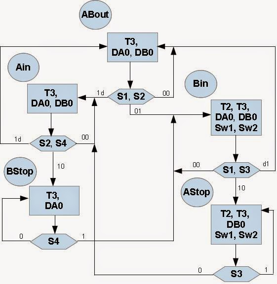
| Fig 1. ASM Diagram of Electric Train Controller |
An ASM chart and State Machine diagram shown in figure 1 (above) and figure 2 contain the same information and describe algorithm of the train controller. In the ASM chart, state names, ABout, Ain, Bin, Bstop, Astop indicate the active and possible states. The rectangles contain the active (High) outputs for the given state. Outputs not listed are inactive (Low). The diamond shapes in the ASM chart indicate where the state machine tests the condition of the inputs (S1, S2, etc.). When two signals are shown in a diamond, they are both tested at the same time for the indicated values.
A state machine classic bubble diagram is shown in Figure 2 below. In the same names "in" and "out" refers to the state of track 2, the track that is common to both loops.
Description of The State Machine for Electric Train Controller
Description of The State Machine for Electric Train Controller
 |
| Fig. 2 State Machine Diagram of Electric Train Controller |